Citroen Xsara – Seat hight adjustment lever repair

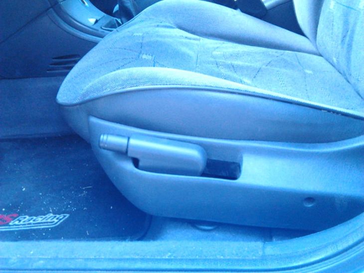
About a week ago getting in the driver’s seat of my 2004 Citroen Xsara Break II, I noticed that the seat hight adjustment lever was pulled up to the highest setting.  At first I thought my wife had left it like that, but as I actually sat on the seat I realised that it sunk back to the lowest position as I put my weight on it, so I figured something was wrong.  The lever switched position accordingly.

Xsara II - Repair seat hight adjustment lever 01

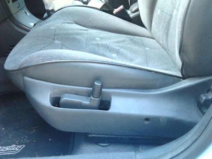
Seat sprung up to the highest position as soon as I got up.

Since then, the seat hight could not be adjusted.  Every time I sat on it, it would sink to the lowest position, only to spring back up to the highest position as soon as I got up.  I did some research on line and although I could not find any detailed instructions on how to fix this problem, I found reports of people having accomplished that, so I thought I’d give it a try.

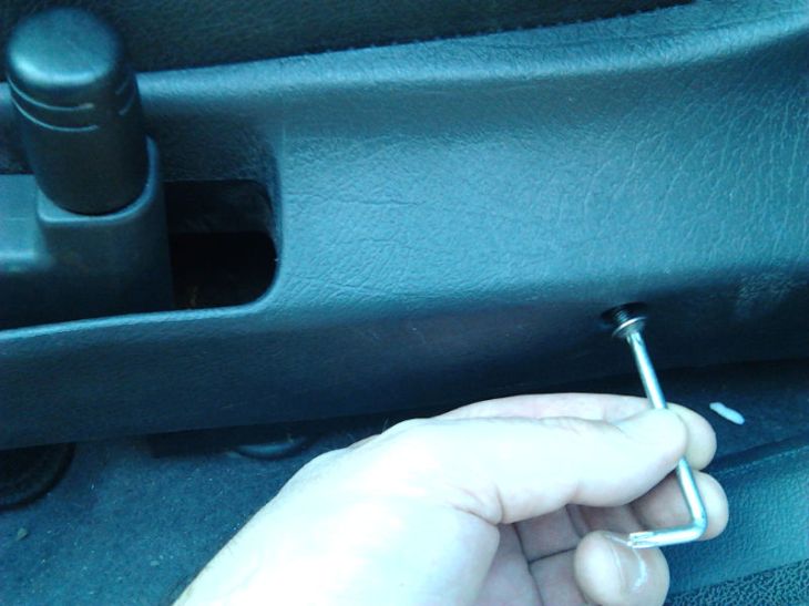
It turned out that fixing it was pretty straight forward and required no special tools, other than a Phillips screwdriver and a Torx key.

First I took the Torx key and removed the screw holding the plastic cover on the side.


Xsara II - Repair seat hight adjustment lever 02Xsara II - Repair seat hight adjustment lever 03

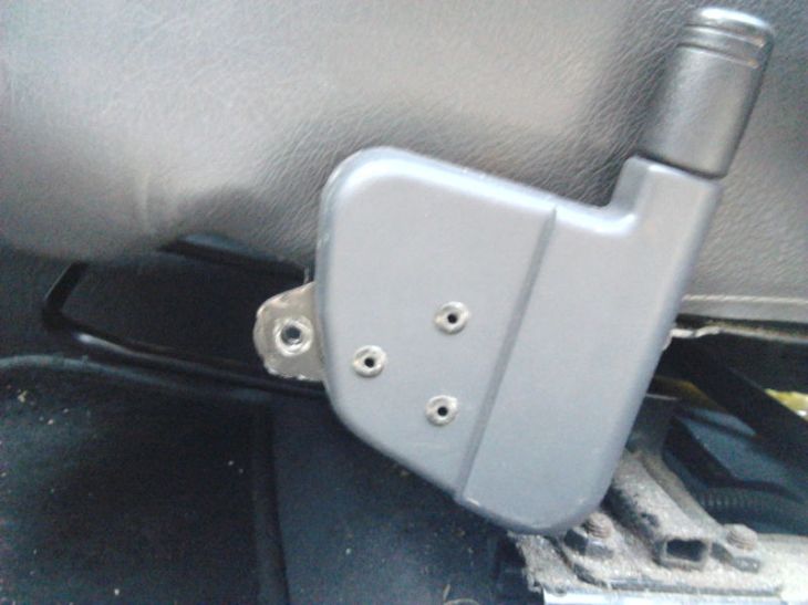
When I removed the screw I could just lift the front part of the plastic cover up and take a look at the lever.

Xsara II - Repair seat hight adjustment lever 04

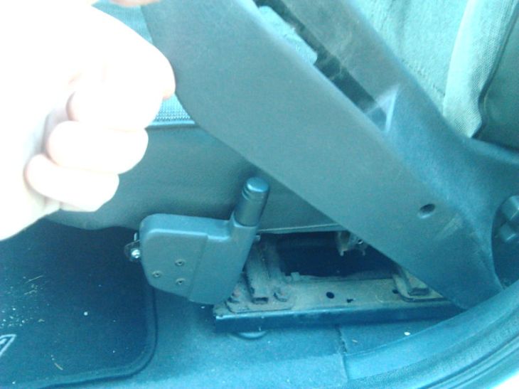
Note that this is picture was actually taken after I had fixed it (hence the lever is properly screwed to the seat chassis)

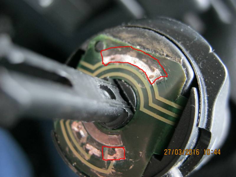
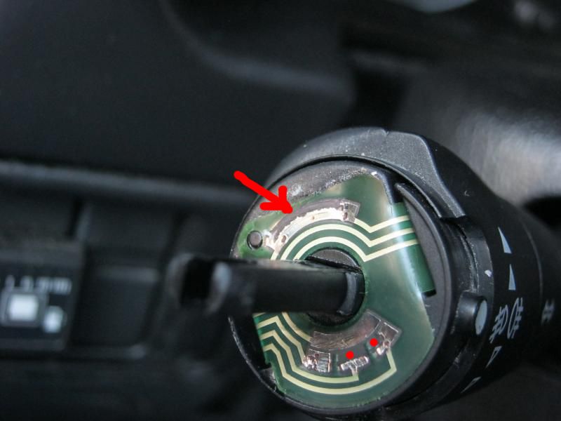
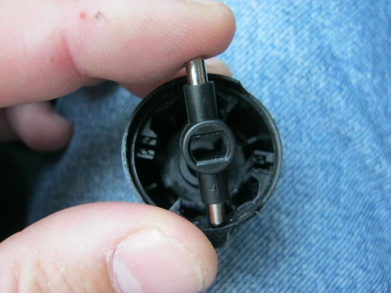
I noticed the hole(s) in front (to the left) of the lever, where a screw seemed to be missing.

Xsara II - Repair seat hight adjustment lever 05

Note that in this picture the hole on the lever’s metal plate is aligned with the corresponding hole on the seat’s chassis.  This is its proper position and it may not have been like that when I first removed the plastic cover.

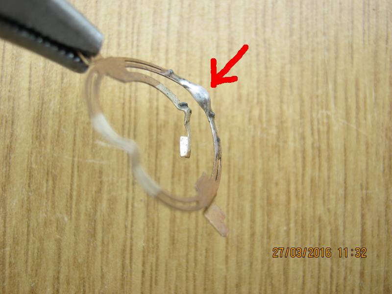
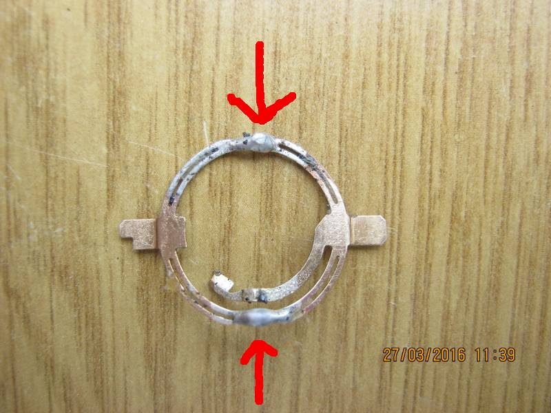
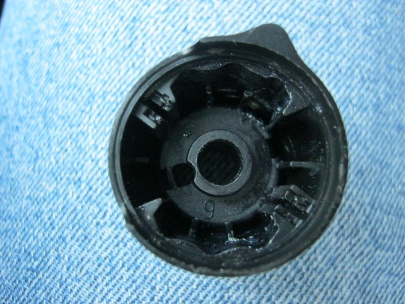
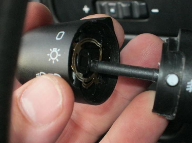
Anyway, I went on to remove the lever by pulling it outwards.  I later realised I probably needn’t have done that.  Although it did help me partly understand how the lever works, it also cost me some time trying to correctly reposition it.  Here’s a couple of pictures to satisfy your curiosity.

Xsara II - Repair seat hight adjustment lever 06Xsara II - Repair seat hight adjustment lever 07

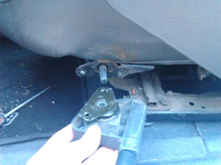
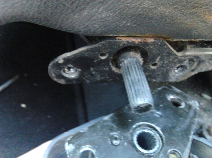
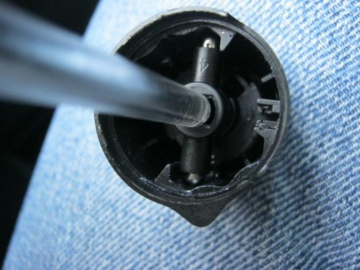
Anyway, doing that I saw there was another screw missing behind (to the right of) the lever.

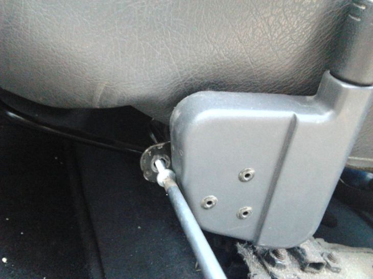
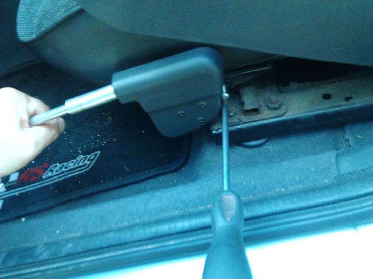
I placed the lever back on the protruding shaft as it normally is when the seat is set at the highest setting, aligned the holes in front (to the left) of the lever and screwed a new screw on. I did not tighten it much though, as I later found out that it would make it difficult to correctly align the holes behind (to the right of) the lever.

Xsara II - Repair seat hight adjustment lever 08

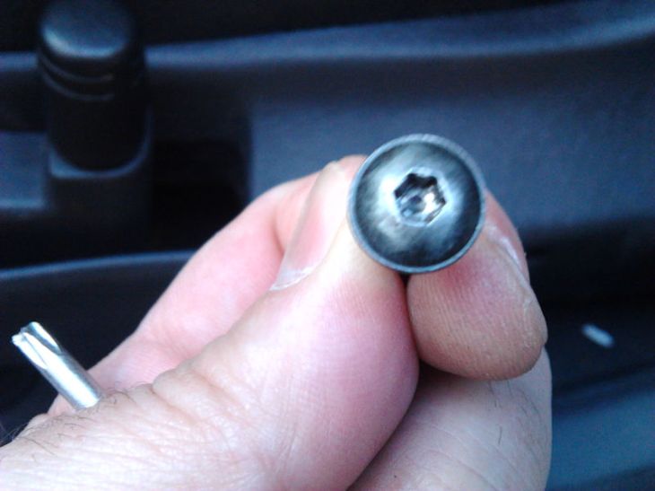
The missing screws were exactly the same size and type as the one I removed from the plastic cover, and I happened to have a couple of those in my tool box, only with a Phillips head, instead of Torx.

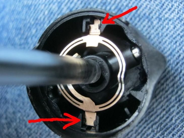
After screwing the first screw I tested the seat hight adjustment and found it once again worked.  I set the seat to the lowest setting and started screwing the second screw on.  As you can see in the picture below, the holes were not perfectly aligned, and I had to “convince” them into place by pulling down on the lever.  Alternatively, one could have someone else sit in the driver’s seat while placing the second screw.

Xsara II - Repair seat hight adjustment lever 09

I then set the seat to the highest setting again, tightened that first (left) screw properly and brought the seat back to its highest setting. After that, it was just a mater of pushing the plastic cover in place over the lever and securing it with its screw.

Xsara II - Repair seat hight adjustment lever 02

And there it was!  The seat hight adjustment lever fixed and the driver’s seat set at the lowest setting again!  Just the way I like it!

Xsara II - Repair seat hight adjustment lever 10

I hope you found this informative and useful.

Cheers!

End of Citroen Xsara – Seat hight adjustment lever repair.

Please remember, this is a record of what I did. YOU ARE RESPONSIBLE FOR YOUR OWN ACTIONS.

Citroen Xsara lights switch repair PART THREE (REPAIR)

OK, long story short, conductive glue did NOT work. Apparently it was neither conductive nor durable enough for the job. Lights kept coming on unexpectedly etc.

I cleaned all the “conductive” glue away from the contacts and here is the damage to the contacts once again.

WORN CONTACTS

This time I thought I’d approach the problem differently. Instead of repairing the worn contacts, I thought I’d try broadening and elongating the pointy tips of the metal ring that rotates on top of the contacts and completes the circuits. The general idea was to force them to sit more firmly on top of the worn contacts.

METALLIC RING

METALLIC RING

I used some soldering wire, flux grease and my soldering gun.

SOLDERING TOOLS

After putting everything back together, I saw I kept having the same problems and I realised that the problem might be related to the fog lights switch. I dismantled the main lights switch (again…) and started fiddling with the fog lights switch, which came off quite unexpectedly pulling an approximately 15cm long flexible printed circuit cable, like the ones you find in mobile phones. At that point I realised I had no choice but to remove the whole ring around the steering wheel column and access the notorious DELPHI 2000 BSI UNIT, in order to reattach the flexible printed circuit cable I had accidentally pulled out.

But first, I thought I’d address the fog lights switch problem, since I was already holding the thing in my hands, in pieces. Here are all the pieces.

FOG LIGHT SWITCH

Notice the metallic spring loaded, bullet shaped objects.

BULLET SHAPED OBJECTS

At that point I felt I was already in over my head, so I thought I’d be brave and try doing it the good old fashioned way. Soldering!

Looking at the main lights switch worn contacts, I needed some flat pieces of copper to solder on to them, to expand them to their original dimensions. I found some in a piece of TV areal cable I had laying around. It was coated with a thin layer of plastic on one side. I brazed that off using my soldering gun and tested conductivity with a multimeter. I cut the necessary pieces to size and, liberally applying flux grease on them, tin coated them on one side.

TINNEDCOPPERSHEET

TINNED COPPER SHEET

I then placed the copper pieces on to the worn contacts with the tin coated side facing the contacts. Holding each piece in place with the tip of a small screw driver, I heated the back (uncoated) side of each copper piece just until the tin coat on the other side became liquid and then quickly removed the soldering iron. When the tin (solder) solidified, it was stuck in place, in contact with the worn contacts. This procedure required some precision and did not allow for many errors with the soldering gun (although I made a couple and fixed them as best I could). I tried to make surfaces as smooth as possible, locally re-heating (re-liquefying) the soldering, being careful not to unsolder the copper pieces from the contacts.

REPAIRED CONTACTS

Contacts on the backside of piece number 5 in the 5th image, corresponding to the fog lights, were not as worn, so I just simply tin coated some of them. During all this soldering, flux grease made all the difference, as it made solder stick to the contacts like crazy.

FOG LIGHT CONTACTS

After I was done with all the soldering, I tested every repaired contact using a multimeter , touching the repaired contact with one multimeter lead and the corresponding contact at the end of the cable with the other multimeter lead (there should be conductivity). I also tested touching each contact (repaired or not) with one multimeter lead and the adjacent contacts at the end of the cable with the other multimeter lead (there should be NO conductivity).

Oh, I also soldered the pointy tips of the second metal ring that rotates on top of the fog lights contacts and completes the circuits.

FOG LIGHT METALLIC RING

Then, there was only the small matter of removing and opening the DELPHI 2000 BSI UNIT. Then, reattaching the flexible printed circuit cable I had accidentally pulled out, to the BSI plastic circuit board. I followed instructions I found on youtube. Each video described a different part of the process. Here is what I found useful:

1) https://www.youtube.com/watch?v=bzGDj0zmLEU : Peugeot 206 lights/wiper switchgear replacement (everything is more or less the same except for the airbag removal).

2) https://www.youtube.com/watch?v=laFmvp8YGE8 : Citroen Xsara Phase 2 (2000-2004) Steering Wheel Airbag Removal

Before re-assembling the BSI unit, I re-assembled the light switch lever. I pulled the flexible printed circuit cable through the corresponding slots of all the parts comprising the lever using tweezers. I then clicked everything together and the light switch lever was ready to reconnect to the BSI unit. Meanwhile, the other lever got disconnected as well. I put both levers back in the BSI casing, making sure all parts fit correctly. I couldn’t get a picture of the thing half assembled with everything in the right place, so I have colour coded picture 12 to show what goes where.

BSI UNIT

I figured that I had to place the levers on the side with the PCB, then connect the cables (making sure the cable contacts actually came in contact with the corresponding metal pins and securing the cable in place with the plastic clip) and then make sure everything goes where it’s supposed to.

I carefully clicked the BSI casing closed, trying to keep things in the right place, and that was it! The hard part was finally over. I put the BSI unit, the steering wheel and the airbag back in place and tested. Mind you, I didn’t get it right the first time. As soon as I reconnected the battery, I noticed the headlights were permanently on. So I had to do it ALL OVER AGAIN. After that, I retested, everything worked great and I was a happy bunny!

I honestly don’t know how well these repairs will hold up, but now I know how to take everything apart and put everything back together, so I am confident that if/when I have the same problem again I can easily fix it again. Or I reckon I can just visit an automobile junkyard, get a used BSI unit and install it myself.

End of Citroen Xsara lights switch repair PART THREE (REPAIR)

Please remember, this is a record of what I did. YOU ARE RESPONDIBLE FOR YOUR OWN ACTIONS.

Citroen Xsara lights switch repair PART TWO (RE-ASSEMBLY)

Picking up where we left off at my previous post Citroen Xsara lights switch repair PART ONE (DISASSEMBLY)

OK, so you got all the lights switch parts in a bowl.

07a

Now it’s time to clean the contacts on the lever. As mentioned in my previous post, Citroen Xsara… (PART ONE DISASSEMBLY), There is an article I found a while back explaining the various types of technology used for the switch (https://citroenc3owners.com/citroen-c3-tips/the-com2000-or-steering-wheel-stalks-an-inside-look-t467.html ). Mine was one of those that that particular article said would not respond to cleaning with some contact cleaning spray.


12

Surprisingly, it worked in my case. For about 9 months I had no problems at all. So give it a go before you try anything more radical. To be honest, this time I noticed that the brass contacts on the flexible printed circuit were very worn, so I thought just spray cleaning them would not do the job again.

My first thought was to use my soldering iron to add some tin to the worn brass contacts, but I immediately dismissed the idea when I realized that I would almost certainly burn through the fine lamination of the flexible circuit and destroy the switch beyond repair. Then it dawned on me: “What if I could do the same thing without the heat?”. After some research on the internet I learned all about conductive inks (you can even homebrew them from charcoal and paint electronic circuits on plain paper)! But the ink would not last long in the switch’s high friction environment, so I researched a bit more and found that there are conductive glues sold quite cheaply over the internet that cure in room temperature and are friction resistant! They are mostly used to repair and/or modify PCBs (circuit boards) and to repair the heated rear windows of cars. Unfortunately at the time of this historic revelation I could not get my hands on any of that glue. So, since the lights switch lever was already disassembled and in a plastic bowl, I ended up spray cleaning the worn contacts once again and reassembling the unit.


08

Here is how you go about doing that.

Take the plastic end cap (1) and attach it to the plastic ring (2) you turn to switch the lights on and off (the one with all the indications on it). There are two small clips opposite each other on the end cap. Make sure you match them to the corresponding slots on the plastic switch ring. Once the two parts click into position, take the whole thing and lay it down so you can see the inside.


13

Now, carefully take the part that makes the light switch click between positions when you turn the lights on and off together with the two metallic, bullet-shaped objects sticking out (3) and try to position it at the centre of the previously assembled piece. To do that, you will have to push the bullet-shaped (and spring loaded) objects inwards with your fingers. This part is VERY tricky because the bullet-shaped objects tend to either go in the wrong way or spring out. Be VERY careful not to lose them!


14

I found that a screwdriver pushing down like in the next picture made things a little easier.

15

Now, take the metal (brass?) ring (4) and place it o top of everything, at the designated positions. Notice that they are designed so that you can secure the metal ring in place. Do not just lay it on top of everything. The metal ring is curved and pointy on one side. This side should be facing upwards and not towards the rest of the assembly.

16

By the way, this pointy side is where electrical contact is made with the flexible circuit.

When everything is in the right place, take the whole assembly and carefully place it on the lever, making sure the indications are facing your way. The lever clip will slide in the assembly and click into position.

17

Your lights switch should be working as usual now.

After about a week, I finally received the conductive glue and started repairing.  I’ll let you know how it worked in another post…

END OF PART TWO (RE-ASSEMBLY)


Please remember, this is a record of what I did, published as a reminder to myself.  YOU ARE SOLELY RESPONSIBLE FOR YOUR OWN ACTIONS.

Put your old economy light bulbs to good use!

put your old economy light bulbs to use

Most households have several old, still working, economy light bulbs just sitting around in the tool closet or in the tool shed.  We usually put them away either because we replace them with LED bulbs or because they are not as bright as they used to be.

However, those old economy light bulbs have a couple of traits that could make them ideal for certain situations.  Being dim, they are more suited for bedrooms, where you’d want something less bright.  Besides, the fact that it takes them a couple of minutes to reach the top of their (somewhat diminished now) capabilities, works perfectly in the bedroom.  They give your eyes the time they need to slowly adjust to the light.  This way, you will no longer feel like someone is flashing a torch light in your eyes every time you wake up and switch the lights on.

😉

Citroen Xsara lights switch repair PART ONE (DISASSEMBLY)

Citroen Xsara Break N2

Citroen Xsara Break N2

OK, so I’m driving my Citroen Xsara Break N2 the other day and the lights come on, all by themselves.  And it’s not the first time this happens!  I had the same problem about a year ago and I finally found the time to fix it.  Back then I used to drive long distances, usually in rural areas at night, so the problem first appeared differently.  My long range headlights (high beam) or fog lights would switch off by themselves.  Fortunatelly regular headlights (dipped beam) and position lights would always stay on, so it was not so much a safety issue.  More of a nuisance.  When the lights started comming ON by themselves during the day, when they were normally switched off, it became irritating. People thought I was signalling them etc.

I searched the web for information on how to remedy the problem, but most would suggest replacing the whole stearing wheel swithes unit (COM2000 unit) with all three levers on it, but I was not prepaired to pay the 250 euro for the part plus whatever citroen would charge to install the thing.  After a lot of digging I came across this page: http://citroenc3owners.com/citroen-c3-tips/the-com2000-or-steering-wheel-stalks-an-inside-look-t467.html .  It helped a lot, as it described the varius types of mechanisms found in most, if not all, citroen car light swithces levers.  I realised that I did not need to replace the whole COM2000 unit (airbag coil and all).  Instead i could repair the swithes on the one particular (lights) lever.

First time I fixed it, I just used some contact cleaning spray. That did the job for about 9 months, but I did not document the procedure.  This time I thought I’d save someone the trouble of scouring through the net for hours for detailed instructions on something relatively easy to do that will save them quite a bit of money.

Here it goes:

When your citroen lights start developing a personality of their own, you will notice the green light at the right of the dashboard blinking, instead of being either on or off.

Green lights indicator blinks

Green lights indicator blinks

Poke the end cap of the lever out using something thin and pointy.  I used a small knife and worked my way around the cap.

Remove the end cap

Remove the end cap

I suspect that in some citroen models this end cap has some usefulness as a button (perhaps for the horn), hence the spring underneath it.  In my Xsara Break N2 that is not the case.

Spring under end cap

Spring under end cap

The rest of the asembly is held together by a clip at the centre of the lever.

Clip at the centre of the lever

Clip at the centre of the lever

Use some sort of tongs or needle-nose pliers to push the two parts of the clip together and BE PREPAIRED TO CATCH THE SPRING LOADED PARTS which will fly out of the asembly as soon as you pull the switch cover out.  The first time I did it I tried wraping a plastic bag around the whole lever, but that complicated things.  Wrapping my palm around the lever and slowly pulling the switch cover out worked best for me.

Use pliers to unclip

Use pliers to unclip

By the way, it’s a good idea to hold some sort of bowl between your legs while doing all this, as i did.  It will give you a place to keep all the small parts together, so you won’t lose any of them, and it might just save you the trouble of combing the seat and floor of the car when some small part slips between your fingers (trust me, at some point it will).

A bowl comes in handy

A bowl comes in handy

This is the part that makes the light switch click between positions when you turn the lights on and off.  Notice the two metallic, bullet-shaped objects sticking out.  They are the spring loaded parts you will have to catch when disassembling and contain when assembling the lever.

Do NOT lose these!!!

Do NOT lose these!!!

And these are all the parts you will end up with when you have finished disassembling the light switch, in the order they are to be reassembled (left to right).

All the parts

All the parts

END OF PART ONE (DISASSEMBLY)


Please remember, this is a record of what I did, published as a reminder to myself.  YOU ARE SOLELY RESPONSIBLE FOR YOUR OWN ACTIONS.