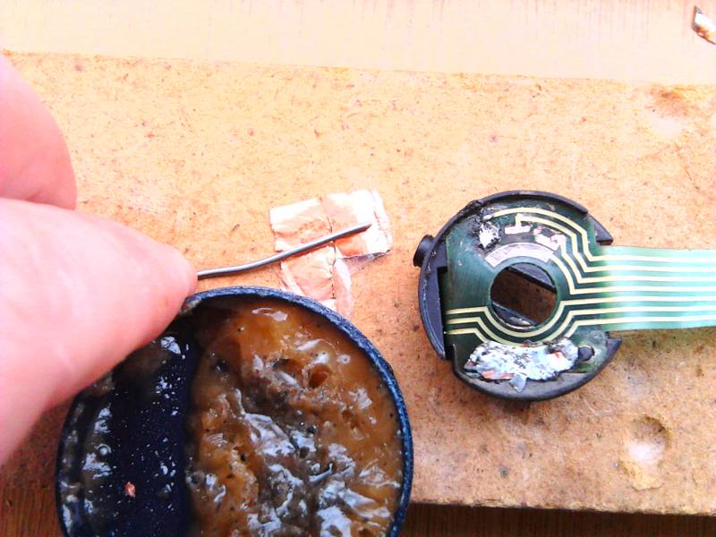
OK, long story short, conductive glue did NOT work. Apparently it was neither conductive nor durable enough for the job. Lights kept coming on unexpectedly etc.
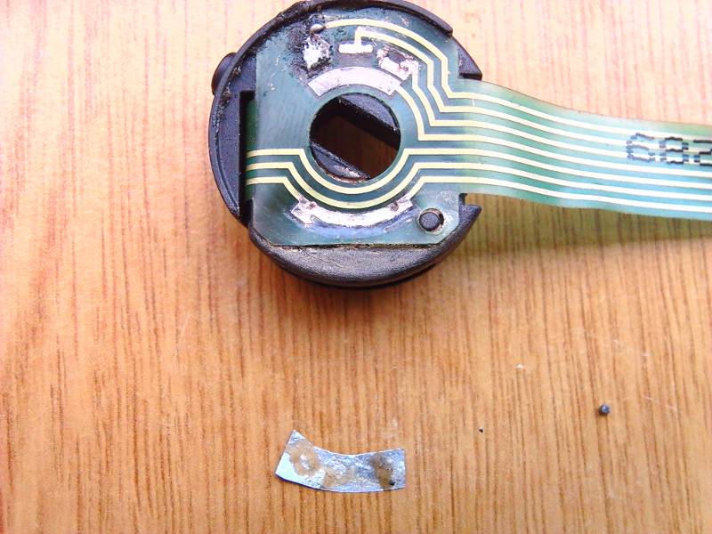
I cleaned all the “conductive” glue away from the contacts and here is the damage to the contacts once again.
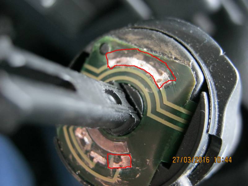
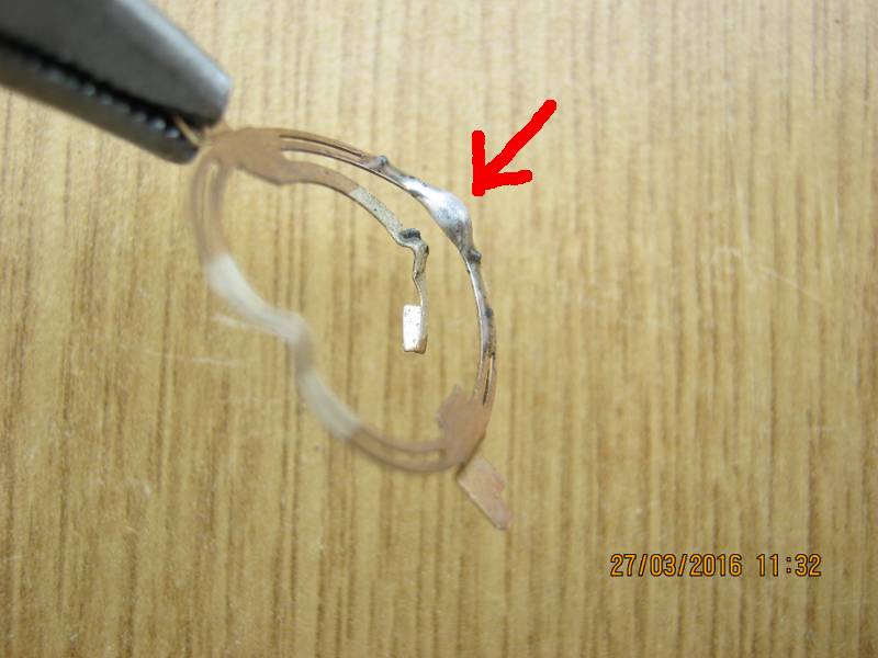
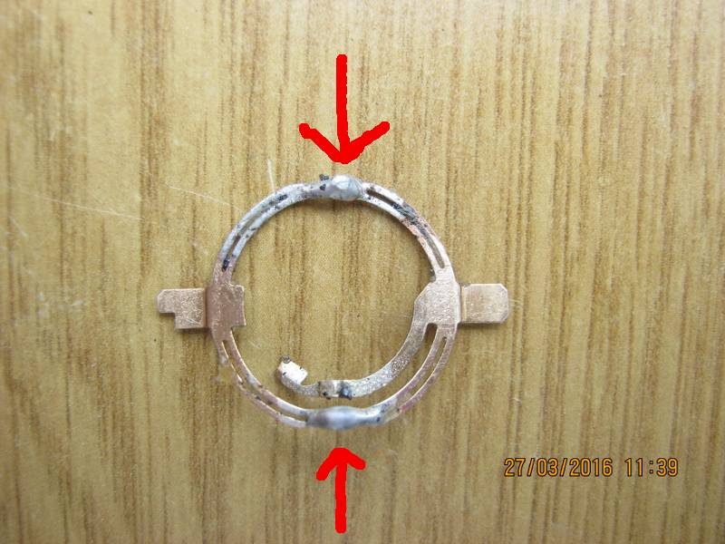
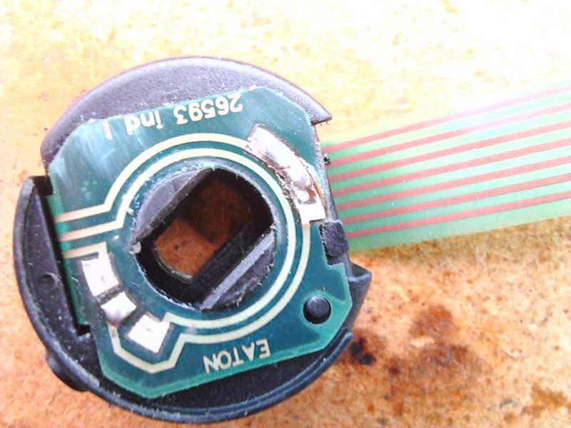
This time I thought I’d approach the problem differently. Instead of repairing the worn contacts, I thought I’d try broadening and elongating the pointy tips of the metal ring that rotates on top of the contacts and completes the circuits. The general idea was to force them to sit more firmly on top of the worn contacts.
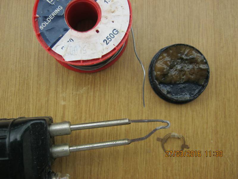
I used some soldering wire, flux grease and my soldering gun.
After putting everything back together, I saw I kept having the same problems and I realised that the problem might be related to the fog lights switch. I dismantled the main lights switch (again…) and started fiddling with the fog lights switch, which came off quite unexpectedly pulling an approximately 15cm long flexible printed circuit cable, like the ones you find in mobile phones. At that point I realised I had no choice but to remove the whole ring around the steering wheel column and access the notorious DELPHI 2000 BSI UNIT, in order to reattach the flexible printed circuit cable I had accidentally pulled out.
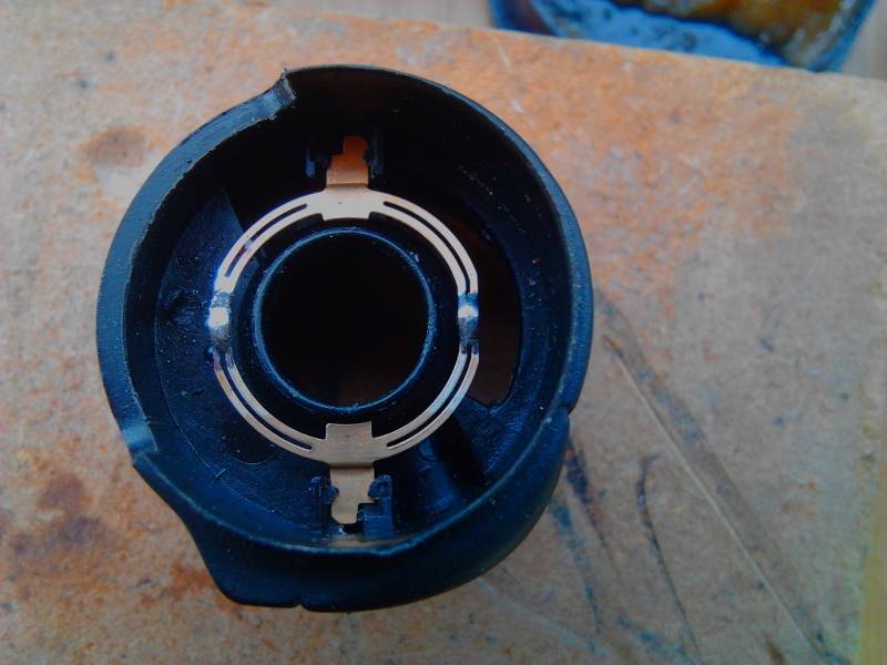
But first, I thought I’d address the fog lights switch problem, since I was already holding the thing in my hands, in pieces. Here are all the pieces.
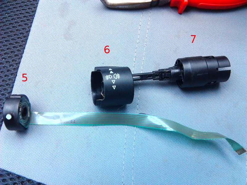
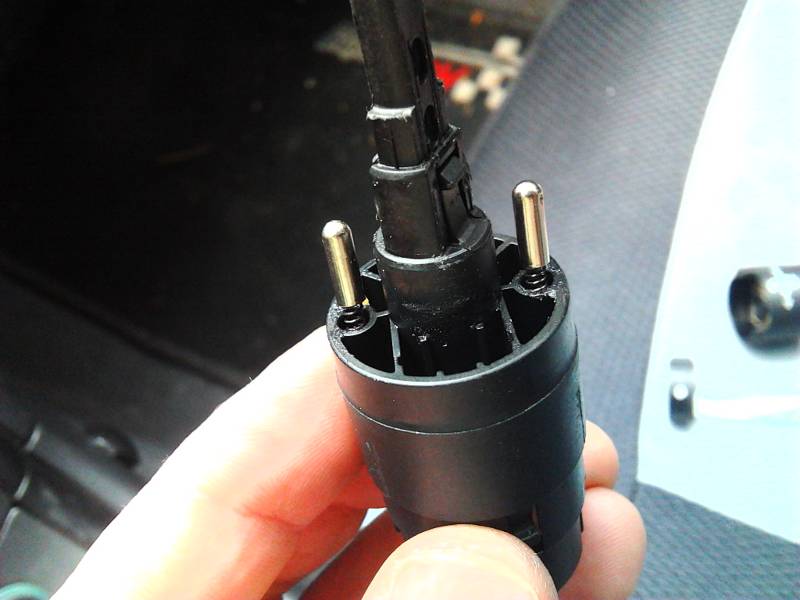
Notice the metallic spring loaded, bullet shaped objects.
At that point I felt I was already in over my head, so I thought I’d be brave and try doing it the good old fashioned way. Soldering!
Looking at the main lights switch worn contacts, I needed some flat pieces of copper to solder on to them, to expand them to their original dimensions. I found some in a piece of TV areal cable I had laying around. It was coated with a thin layer of plastic on one side. I brazed that off using my soldering gun and tested conductivity with a multimeter. I cut the necessary pieces to size and, liberally applying flux grease on them, tin coated them on one side.
I then placed the copper pieces on to the worn contacts with the tin coated side facing the contacts. Holding each piece in place with the tip of a small screw driver, I heated the back (uncoated) side of each copper piece just until the tin coat on the other side became liquid and then quickly removed the soldering iron. When the tin (solder) solidified, it was stuck in place, in contact with the worn contacts. This procedure required some precision and did not allow for many errors with the soldering gun (although I made a couple and fixed them as best I could). I tried to make surfaces as smooth as possible, locally re-heating (re-liquefying) the soldering, being careful not to unsolder the copper pieces from the contacts.
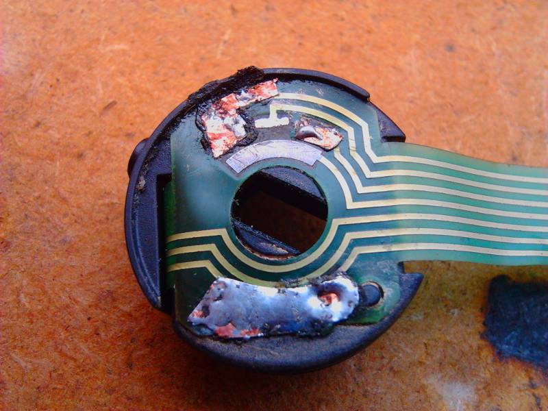
Contacts on the backside of piece number 5 in the 5th image, corresponding to the fog lights, were not as worn, so I just simply tin coated some of them. During all this soldering, flux grease made all the difference, as it made solder stick to the contacts like crazy.
After I was done with all the soldering, I tested every repaired contact using a multimeter , touching the repaired contact with one multimeter lead and the corresponding contact at the end of the cable with the other multimeter lead (there should be conductivity). I also tested touching each contact (repaired or not) with one multimeter lead and the adjacent contacts at the end of the cable with the other multimeter lead (there should be NO conductivity).
Oh, I also soldered the pointy tips of the second metal ring that rotates on top of the fog lights contacts and completes the circuits.
Then, there was only the small matter of removing and opening the DELPHI 2000 BSI UNIT. Then, reattaching the flexible printed circuit cable I had accidentally pulled out, to the BSI plastic circuit board. I followed instructions I found on youtube. Each video described a different part of the process. Here is what I found useful:
1) https://www.youtube.com/watch?v=bzGDj0zmLEU : Peugeot 206 lights/wiper switchgear replacement (everything is more or less the same except for the airbag removal).
2) https://www.youtube.com/watch?v=laFmvp8YGE8 : Citroen Xsara Phase 2 (2000-2004) Steering Wheel Airbag Removal
Before re-assembling the BSI unit, I re-assembled the light switch lever. I pulled the flexible printed circuit cable through the corresponding slots of all the parts comprising the lever using tweezers. I then clicked everything together and the light switch lever was ready to reconnect to the BSI unit. Meanwhile, the other lever got disconnected as well. I put both levers back in the BSI casing, making sure all parts fit correctly. I couldn’t get a picture of the thing half assembled with everything in the right place, so I have colour coded picture 12 to show what goes where.
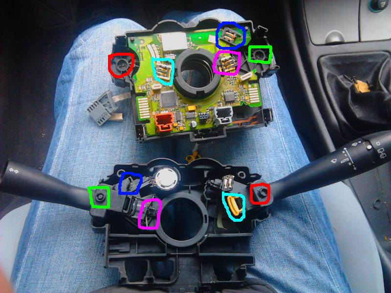
I figured that I had to place the levers on the side with the PCB, then connect the cables (making sure the cable contacts actually came in contact with the corresponding metal pins and securing the cable in place with the plastic clip) and then make sure everything goes where it’s supposed to.
I carefully clicked the BSI casing closed, trying to keep things in the right place, and that was it! The hard part was finally over. I put the BSI unit, the steering wheel and the airbag back in place and tested. Mind you, I didn’t get it right the first time. As soon as I reconnected the battery, I noticed the headlights were permanently on. So I had to do it ALL OVER AGAIN. After that, I retested, everything worked great and I was a happy bunny!
I honestly don’t know how well these repairs will hold up, but now I know how to take everything apart and put everything back together, so I am confident that if/when I have the same problem again I can easily fix it again. Or I reckon I can just visit an automobile junkyard, get a used BSI unit and install it myself.
End of Citroen Xsara lights switch repair PART THREE (REPAIR)
Please remember, this is a record of what I did. YOU ARE RESPONDIBLE FOR YOUR OWN ACTIONS.

Brilliant set of instructions – thanks for making them. One question: Was the reason that your lights were on after the first full re-assembly because the ribbon was the wrong way around?
LikeLike
Thanks Phil! Sorry it took me so long to answer this. To be honest, I didn’t think anyone would actually read through the whole thing, or ask any questions about it.
Anyway… I don’t think I placed the ribbon the wrong way around. I’m not sure it would work at all, if that were the case. I’ll check if it does, next time I take it apart. I must admit, though, you got me thinking…
LikeLike
Phil, I thought again about your question and I just remembered what happened. The headlights stayed on because I hadn’t correctly paired the plastic slider and phrong marked with magenda colour in picture 12. I should have done that before clicking the two parts of the BSI casing together. I hope this helps.
LikeLike